CAD-Line > DXF tab
See also: File menu > Open DXF-File, DXF-Element dialog
Use the CAD-Line > DXF tab to:
•Display* a DXF-Drawing •Align the DXF-Drawing with the CAD-Line •Edit the color of the DXF-Drawing •Convert DXF Entities in the DXF-Drawing to MechDesigner sketch-elements •Remove the DXF-Drawing from the CAD-Line |
* Before you can display a DXF-Drawing, you must import it with File menu > Open DXF file. We add DXF-element to the Assembly-Tree, which is the container for the DXF-Drawing.
DXF Terminology
Term : |
Definition |
|---|---|
DXF : |
Drawing eXchange Format. DXF is a CAD data file format for sharing drawing data universally across CAD applications. |
DXF-Drawing : |
The drawing that you want to import then display in the graphics-area in MechDesigner. |
DXF-Element : |
A DXF-Element is a container for a DXF-Drawing you import when you do File menu > Open | DXF file-type When you do File menu > Open | DXF file-type, we add a DXF-Element to the Assembly-Tree as a container for a DXF-Drawing that you want to display in the graphics-area. |
CAD-Line : |
The element in a Part that you can edit to display a DXF-Drawing. You can do Add CAD-Lines to display other DXF-Drawings in a Part. |
DXF-Outline : |
A sketch that we use to efficiently display a DXF-Drawing. You cannot edit a DXF-Outline. |
DXF-Entity : |
Points, Arcs, and Lines are DXF-Entities in a DXF-Outline. You can use the CAD-Line dialog to convert Arc and Line DXF-Entities to regular MechDesigner Arc and Line sketch-elements. |
CAD-Line dialog
DXF tab

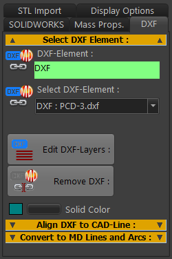
CAD-Line dialog > DXF tab
 |
|
|
|
For example: DXF : PCD-3.DXF DXF is the name of the DXF-element that you add to the Assembly-Tree when you do File menu > Open DXF file-type. It is the container for the DXF-Drawing. PCD-3.DXF is the name of the DXF-Drawing that is “in” the DXF-Element. If you cannot see the DXF-Drawing:
|
||
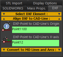 |
Align the DXF-Drawing with the CAD-Line, select two(2) DXF-Points.
|
||
Notes:
|
|||
![]() Convert DXF Entities to MD Lines and Arcs
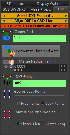
Convert DXF Entities to MD Lines and Arcs
You cannot edit the DXF entities (DXF Line, DXF Arc, and DXF Point) - they are dumb. You can use this separator to copy the shape of DXF entities to MechDesigner Line, Arc, and Point sketch-elements. After you convert them to MechDesigner sketch-elements, you can optionally remove the original DXF entities. |
||
 |
|
|
TOP-TIPS:
|
||