Application-Settings
Use Application-Settings to edit the working environment and other working parameters.
See also: Application-Settings, Themes, Styles, and the Save and Load buttons
|
Click Edit toolbar > Application-Settings OR Click Edit menu > Application-Settings |
|
|
The Application Settings dialog is now open. |
|
Application-Settings dialog:

Application Settings dialog
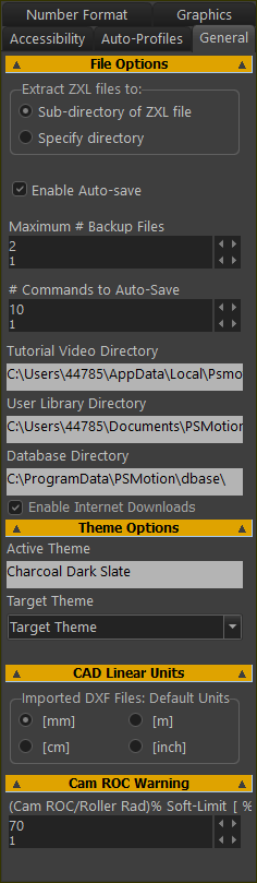 |
File Options See also: ZXL file-type. Extract ZXL Files to: ◉sub-directory of ZXL file: we add for you a sub-directory to the ZXL file, and extract the files in the ZXL file to the new sub-directory. ◉Specify directory: you specify a path in which to extract files that are in the ZXL file. ☑ Enable Auto-Save: Enable to automatically save the active model, after # Commands to Auto-Save AND overwrite the active model in RAM.
Maximum # (Number) of Backup files When you Enable Auto-Save, you can edit the number of backup files. You will see new files on your hard drive: for example: CXL.1, MTD.1 (youngest); CXL.2, MTD.2 ; ... CXL.#, MTD.# (oldest) When you open a model, we do the steps in the example here. # (Number) Commands to Auto-save When you also Enable Auto-Save, this parameter controls the number of commands between each Auto-Save event. See the example here of an Auto-Save event. User Library directory - click the box to specify the path for your User Library directory Allow Internet Downloads : enable to allow downloads. Theme Options Active Theme: After you select a Target Theme, the box shows the Theme. Target Theme: Select from: •Charcoal Dark Style, Windows, Aqua Light Slate, Windows10 Dark, Tablet Dark, Slate Classico, Windows 10 Slate Gray, and Windows 10.
CAD Linear Units Imported DXF Files: units We use these units to scale a DXF-Drawing that you import. The scale is 1:1 when the units are equal to those of the original DXF-Drawing that you import. See also: Open DXF File, Edit DXF-Element Cam RoC Warning IF
•The Cam-Profile is more likely to Undercut •The Cam-Profile is red in the graphics-area as a WARNING ONLY - a soft-limit. |
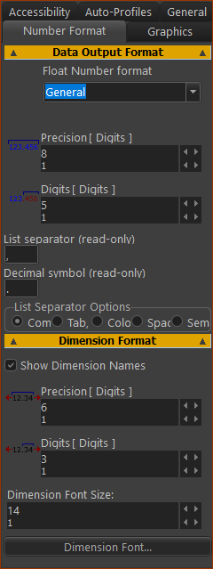 |
Note: Precision of calculations do not change when you edit these parameters. Data Output Format Data-format of data you can save to your hard disk. E.g. Data from a Graph FB or a Cam-Coordinates FB. Float Number Format: See Precision and Digits - see below List separator (read-only) - the regional character that separates values. For example, “,” in a CSV file. Decimal Separator (read-only) - the character that separates the integer and fractional parts of a number. For example, “.” in 12.3456 List Separator Options - see Select a “List Separator” for data exported or saved to a file- e.g. a save Cam-Coordinates as a TXT file. Dimension Format ☑ Show Dimension Names If you do not enable Show Dimension Names, you can click on a dimension to see its name in the Selection-Window. Data-format of dimensions, in the graphics-area: •Precision and Digits - see below •Dimension Font Size - experiment (typically 14) •Dimension font - click to select a font
|
||||||||||||||||||||||||||||||||
Notes:
|
|||||||||||||||||||||||||||||||||
List separator options Select Separator for export of data files. E.g. Save 2D-Cam Coordinates as X-Y Points.
|
|||||||||||||||||||||||||||||||||
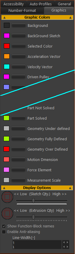 |
Display colors Edit the color of the symbols in the graphics-area. Recommended colors: •Part Not Solved (not kinematically-defined) is a blue •Part Solved (kinematically-defined) is a green XY-axes in the Mechanism-Editor and Part-Editor are: •Red: X–axis •Green: Y–axis XYZ-axes (Triad) at the origin of the Model-Editor: •Red: X–axis •Green: Y–axis •Blue: Z-Axis Display Options There are two sliders << Low (Sketch Quality) High >> Drag the slider to the left to decrease or to the right to increase the number of facets around Circle and Arc sketch-elements. << Low (Extrusion Quality) High >> Drag the slider to the left to decrease or to the right to increase the number of facets around Extrusions ☑Show Function-Block Names (see images left) Enable to show the name of each Function-Block above the FB icon in the graphics-area. This is more helpful if you rename Function-Block - see Rename element ☑Enable Anti-aliasing* Enable to remove the jagged edges from the elements in the graphics-area. Line-Width Edit the Line-Width to increase or decrease the thickness of sketch-elements. * Anti-aliasing : is OK for Lines, is bad for Arcs, Circles, and is very bad for Gears. Generally, I do not Enable Anti-Aliasing. |
 Do not display Function-Block names  Display Function-Block names  Rename and Display Function-Blocks |
|
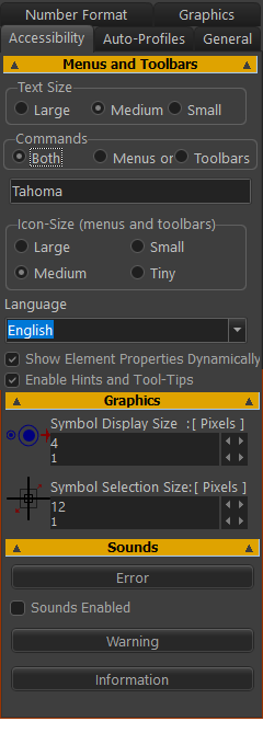 |
Menus Text Size - in menus and dialog Large - too big? ; Medium - recommended ; Small - OK? Commands - new in MD17 Both (show Menus AND Toolbars) ; Menus only ; Toolbars only Icon Size Large (48×48 ) - too big? ; Medium (32×32) - recommended ; Small (24×24)OK ; Tiny (16×16) - too small? Note : If the toolbars do not show correctly, re-start MechDesigner. Show Element-Properties Dynamically To show Element-Properties in the Extended-Hints box when you move your mouse over elements. However, this may annoy you when there are many elements. Note: To show the Element-Properties in a dialog, CTRL+Click the element Enable Hints with Tool Tips See also Help menu Show the hint when you move your mouse over a command icon. We also show the hint in the Feedback Area. Language (from MD17-1-136) English, Italian, German, French, Spanish, Portuguese, Dutch, Polish, Russian, Japanese, Chinese. |
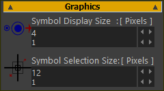 |
Graphics Symbol Display Size (Pixels): The size of the symbols that represent the elements in the graphics-area. Symbol Selection Size (Pixels): The size of the pointer “pin-head”. Increase the size to make it easier to select an element, but, at the same time, you may also select more than one element. |
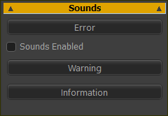 |
Sounds ☑Sounds Enabled Enable the check-box to hear a different sound with each message in the Feedback-Area. There are many messages! Click the buttons to hear the sound for the three types of messages. |
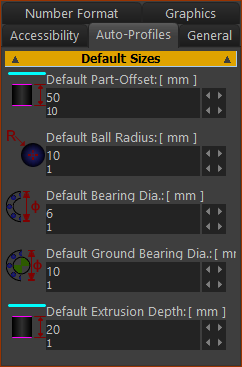 |
Default Sizes Default Part-Offset (default = 0) The default offset of all Profile/Extrusions you add to a Part. Default Ball Radius The default size of the Ball-Joint symbol. See also: Add Ball-Joint ; Ball-Joint dialog Default Bearing Dia. (dia. = diameter) Default Ground Bearing Dia. (dia. = diameter) The default dimension given to arcs at Pin-Joints when you do Add Auto-Profile(s). See also: Add Auto-Profiles Default Extrusion Depth The default Extrusion-Depth parameter in the Extrusion dialog. See also: Add Auto-Profile ; Add Auto-Profiles ; Extrusion dialog |