Conjugate-Cam FB
See: Add Conjugate Cam FB.
What is a Conjugate Cam?
 A Conjugate Cam pair |
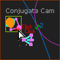
Conjugate Cams (typically two Cams) rotate on one shaft, with each cam in contact a Follower-Roller, and in which the Follower-Rollers are rigidly attached to one Follower-Part. For example: In the image, the blue and orange Cams rotate together on one shaft (the shaft is hollow!). The blue Cam-Profile is in continuous contact with the blue Follower-Roller, and the orange Cam-Profile is in continuous contact with the orange Follower-Roller. The two Follower-Rollers are rigidly attached to the green Follower-Part. |
Why use a Conjugate Cam FB?
Typically, one Cam is the Power-Source for the Follower-Part and kinematic-chain. However, if Conjugate Cams are the used there are two Cams that will be the Power-Source at different points in the machine-cycle. You must add, edit, and configure a Conjugate Cam FB and then select the Conjugate-Cam FB as the Power-Source. Then, the Power-Source can switch between the Cams over the machine-cycle. A Groove Cam is also a conjugate-cam. You cannot select the Inner-Cam and Outer-Cam from one 2D-Cam as the Power-Source. To model a Groove-Cam and its force and stress analysis over a machine-cycle, you need to add two co-axial Follower-Rollers and two 2D-Cams. You must select the Inner Cam of one 2D-Cam, and the Outer Cam of the other 2D-Cam. Then add, edit and select the Inner-Cam and Outer-Cam in the Cam-Conjugate dialog, and select the Cam-Conjugate FB as the Power-Source. |
2D-Cam Work-flow
Before you can start this work-flow, you need to: add a kinematic-chain for the Cam-Part and a kinematic-chain for the Follower-Part ; add a Follower-Roller, or, if you need to model Conjugate Cams and add two Follower-Rollers (even if Concentric for a Groove-Cam) ; add Profile elements to the Follower-Rollers ; add mass-properties to the Parts; develop the motion design. The kinematic-chains with the Follower-Part and the Cam-Part must be kinematically-defined. |
|
Action |
Help Topic |
1.Add a 2D-Cam; or if Conjugate Cams then 2 × 2D-Cams; or if a Groove-Cam then two concentric (co-axial) Follower-Rollers with one for the Inner-flank only, and the one for the Outer-flank only. |
see Add 2D-Cam |
If the new 2D-Cam is one of two Conjugate-Cams, or it is one flank of a Groove-Cam, then: |
|
i.Add a Conjugate-Cam FB ii.Open the Conjugate-Cam dialog and select a flank form each 2D-Cam |
|
2.In the Kinematics-Tree, Configure the Power-Source for the kinematic-chain with the Follower-Part to select the 2D-Cam or a Conjugate-Cam FB as the Power Source |
|
3.Edit the 2D-Cam: to open the 2D-Cam dialog: review Display, Properties, Roller-Life, Cam-Life tabs |
see 2D-Cam dialog |
4.Add a Cam-Data FB (or two if a Conjugate-Cam or a Groove-Cam) |
see Add Cam-Data FB |
5.Edit the Cam-Data FB to link it to a 2D-Cam - close the dialog |
see Cam-Data dialog |
6.Connect wires from one or more output-connectors of the Cam-Data FB to a Graph FB |
|
7.Open the Graph FB to analyze the 2D-Cam: Contact-Force, Maximum Shear-Stress, Radius-of-Curvature, Pressure-Angle, Sliding-Velocity. |
|
8.Edit the Cam-Data FB again to calculate the Cam's Coordinates. |
|
|
To open the Conjugate-Cam dialog:
|
|
The Conjugate-Cam dialog is now open. |
||
Conjugate-Cam dialog
 Conjugate-Cam dialog |
||
In the graphics-area or Assembly-Tree: You must select an Inner-Flank or Outer-Flank from two 2D-Cams
|
||
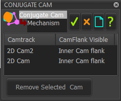 The two 2D-Cams are in one kinematic-chain and must be capable of being the Power-Source for one other kinematic-chain. Each 2D-Cam drives the Inner-Cam-Flank OR the Outer Cam-Flank.
Note 1 : If the 2D-Cams you select do not drive the same Follower-Part, you get this message in the Feedback Area. Message 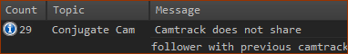 To do Force Analysis of the Conjugate Cams, you must select the Conjugate-Cam FB in the Configure Power Source dialog. To remove a 2D-Cam
|
Select Conjugate Cam in the Configure Power Source dialog
 DEFAULT: Configure Power Source dialog |
|
Configure the Power Source
Now you can do Contact-Force Analysis for the Conjugate-Cams. |
|
 Conjugate-Cam as the Power-Source |