Cam-Data FB > Cam-Coordinates
See Add Cam-Data FB
Use a Cam-Data FB to calculate Cam-Coordinates for a Cam-Profile.
Calculate the Inner, Outer, and/or Pitch-Center Cam-Profiles as: •XY-Points Export a Cam-Profile directly to SolidWorks as XY-Points or BiArcs. Save the Cam-Coordinates to your hard-drive with these file types: •.TXT - XY-Points or BiArcs •.CSV - XY-Points or BiArcs - see Note •.DXF - XY-Points or BiArcs •.SLDCRV (use to import to SOLIDWORKS using its “Curve through XYZ Points” dialog) •.STP : see also Options for: Save Cam as a STEP file Note 1
Note 2
|
2D-Cam Work-flow
Before you can start this work-flow, you need to: add a kinematic-chain for the Cam-Part and a kinematic-chain for the Follower-Part ; add a Follower-Roller, or, if you need to model Conjugate Cams and add two Follower-Rollers (even if Concentric for a Groove-Cam) ; add Profile elements to the Follower-Rollers ; add mass-properties to the Parts; develop the motion design. The kinematic-chains with the Follower-Part and the Cam-Part must be kinematically-defined. |
|
Action |
Help Topic |
1.Add a 2D-Cam; or if Conjugate Cams then 2 × 2D-Cams; or if a Groove-Cam then two concentric (co-axial) Follower-Rollers with one for the Inner-flank only, and the one for the Outer-flank only. |
see Add 2D-Cam |
If the new 2D-Cam is one of two Conjugate-Cams, or it is one flank of a Groove-Cam, then: |
|
i.Add a Conjugate-Cam FB ii.Open the Conjugate-Cam dialog and select a flank form each 2D-Cam |
|
2.In the Kinematics-Tree, Configure the Power-Source for the kinematic-chain with the Follower-Part to select the 2D-Cam or a Conjugate-Cam FB as the Power Source |
|
3.Edit the 2D-Cam: to open the 2D-Cam dialog: review Display, Properties, Roller-Life, Cam-Life tabs |
see 2D-Cam dialog |
4.Add a Cam-Data FB (or two if a Conjugate-Cam or a Groove-Cam) |
see Add Cam-Data FB |
5.Edit the Cam-Data FB to link it to a 2D-Cam - close the dialog |
see Cam-Data dialog |
6.Connect wires from one or more output-connectors of the Cam-Data FB to a Graph FB |
|
7.Open the Graph FB to analyze the 2D-Cam: Contact-Force, Maximum Shear-Stress, Radius-of-Curvature, Pressure-Angle, Sliding-Velocity. |
|
8.Edit the Cam-Data FB again to calculate the Cam's Coordinates. |
|
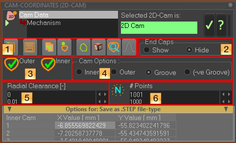
Cam-Data dialog: Cam-Coordinates
If you see “Select a Cam to activate this form”, then click a 2D-Cam in the Assembly-Tree or graphics-area to link it to the Cam-Data FB - see Cam-Analysis |
 |
or
See also: Options for: Save as STEP file-type . |
 Click icon
|
||
|
|
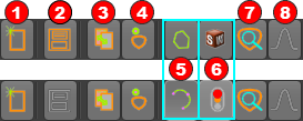
Clear ALL coordinates from the table |
|
|
Save Cam-Coordinate data as: •STP(STEP)- •DXF •CSV •TXT •SLDCRV (SOLIDWORKS Curve file, tab delimited ) - XY Points + Z-data = 0 Note: If this icon is not enabled, make sure Plate-Radius is larger than the Maximum Radius of the Outer Cam. OR: Click Inner or Outer to recalculate the Cam-Coordinates of the Cam-Profile, then, click Inner or Outer again, to calculate the Cam-Coordinates of the Cam-Profile you actually want. See STEP File Options. |
|
|
Copy the Cam-Coordinates to your clipboard |
|
If Cam Option in |
|
|
|
Calculate Cam-Coordinates for the Inner Cam-Profile. Calculate Cam-Coordinates for the Outer Cam-Profile. Calculate Cam-Coordinates for the Pitch-Curve (XY-Points only). |
|
Click |
|
|
|
Calculate as XY-Points You enter the # Points We calculate the XY Coordinates of the Cam-Profile for the number-of-Points at equal increments of the Master Machine Angle. |
|
Calculate as BiArcs (see BiArcs) You enter the BiArc Error We calculate the BiArcs so that the maximum error between the cam we calculate and the true Cam-Profile (we also calculate!) is less than, or equal to, the BiArc-Error. |
|
|
Before you click this button, make sure that SOLIDWORKS is open and the active SOLIDWORKS document is a part document (.SLDPRT). |
|
|
|
We export the BiArcs to SOLIDWORKS as Arc sketch entities, OR We export the XY-Points to SOLIDWORKS and instruct SOLIDWORKS to use the XY-Points to add a Curve feature. In a SOLIDWORKS sketch, you can use Convert-Entities to convert the Curve feature to a Spline sketch entity. See also Note 4 |
|
Usually, we calculate for you the XY Points automatically Usually, we calculate for you the Bi-Arcs automatically, but it takes more time to complete. If the Traffic-Light is RED, click the Traffic-Light icon again. |
|
|
|
Display a preview of the Cam-Profile. |
|
|
Read-only - the cam is “Open” or the cam is “Closed”. |
End Caps relate only to Slot-Cams, also known as Linear-Cams, or Ramp-Cams. Top-Tip - Save a Slot-Cam as a STEP file if it will not transfer to SolidWorks. |
|
 End-Caps - Show |
Show or Hide End-Caps |
End-Caps work well when the independent axis to the Follower moves in one direction only - see image “End-Caps - Show” If the independent axis changes its direction in the middle of its travel, you see False End-Caps in the middle of the Slot-Cam. - see image: “Slot-Cam with 'False' End-Caps”. Before you export Cam-Coordinates we recommend you add a dummy slot-cam - and move the main axis of the Slot-Cam in one direction at Constant-Velocity, over one machine-cycle. To make sure the Constant-Velocity is correct: 1.Connect a wire from a Linear-Motion-FB to a Gearing FB 2.In the Gearing FB, enter a Gearing Ratio = Linear Travel distance of Slot-Cam / 360). 3.Connect a wire from the Gearing FB to the Motion-Dimension FB as the motion of the Slot-Cam. As the MMA increases from 0 to 360, the Cam travels from 0 to Maximum Travel distance of Cam (mm). |
|
 Slot-Cam with 'False' End-Cams |
|
 End-Caps - Hide |
|
|
The cam-coordinates have been calculated. The Radius of the Follower-Roller × % Cam RoC Soft-Limit is greater than the minimum Radius-of-Curvature - see 2D-Cam dialog |
|
The cam-coordinates have not been calculated - Usually after you change from # Points to BiArc Error, or vice-versa. |
|
It is not possible to calculate the cam-coordinates correctly, Possibly because of undercutting. |
|
The cam-coordinates have been calculated. The Radius of the Follower-Roller × % Cam RoC Soft-Limit is less than the minimum Radius-of-Curvature - see 2D-Cam dialog - Undercutting is possible. |


Calculate, Display, and/or Save the Cam-Coordinates: |
|
|
•Inner Cam-Profile ONLY |
|
•Outer Cam-Profile ONLY |
|
•Groove-Cam If you select Groove-Cam AND if you toggle |
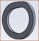 |
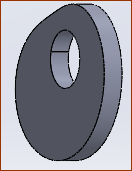
•Negative-Groove The Negative-Groove option applies only when you save the Cam as a STEP file-type - see The STEP file is the space filled by the path of the Follower-Roller along the Cam-Profile (plus Radial Clearance). Note: This is not the same as a Rib Cam. You need to model a Rib-Cam with Follower-Rollers, with one each side of the Rib. |
 Example Radial-Clearance  Cam with 0.2mm Radial Clearance |
See also : 2D-Cam dialog > Parameters tab > Cam Range and Radius Radial Clearance (mm) Default = 0 , Negative or Positive Positive Value - we re-calculate the cam for you to give a clearance between the Follower-Profile and the Cam-Profile. AND: Negative Value - we re-calculate the cam for you to give an interference between the Follower-Profile and the Cam-Profile. |
Applications: Groove-Cam - add clearance (Positive Value) for a Follower-Roller in a Groove cam-type (See Note ) Conjugate-Cam - to add a small clearance (Positive Value) to compensate for tolerances in the cam assembly. Rough-Cut - to oversize an Inner-Cam or undersize an Outer-Cam for a Rough-cut. Radial-Clearance should be a Negative-Value Note: Frequently, Stud-type Follower-Rollers have a dimensional tolerance negative bias - for example, . You may consider that to be enough clearance. |
|
Max Chord-Error with BiArcs |
Apply this maximum BiArc-Error between the Cam-Profile we calculate with BiArcs and the true cam-profile. |
Number of XY Points |
Calculate these number of points for the Cam-Profile at equal increments of the Master-Machine Angle. |
Options for: Save as .STEP file-type
Edit these parameters before you save a cam as a STP (STEP) file. 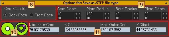 |
|
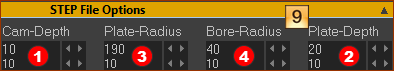
![]() Dimensions for STEP file ONLY
Dimensions for STEP file ONLY
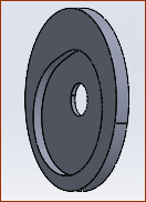
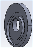
These images show the features of a Groove-Cam that has been exported and opened in SolidWorks:
|
|
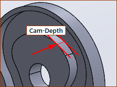 |
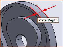
The depth of the Groove Cam cut into the Cam-Plate. The width of the Cam-Flanks. Minimum Plate-Depth – Cam-Depth ≥ 2 mm |
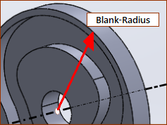 |
The radius of the Cam-Plate, when you select: Outer or Groove-Cam |
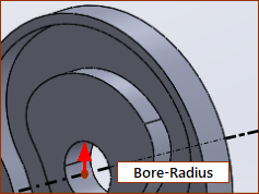 |
The radius of the hole through the center of the Cam-Plate |
 |
The total depth, or thickness, of the Cam-Plate. |
![]() Schematics of Cam type; Are the Dimensions OK or Not-OK?
Schematics of Cam type; Are the Dimensions OK or Not-OK?
Status of Cam, Blank-Radius and Bore-Radius relative to Cam-SizeThe Plate-Radius The Bore-Radius |
|
|
|
|
|
|
|
|
|
|
|
|
|
|
You can save the STEP file. |
|
You can NOT save the STEP file. |
|
|
|
You can NOT save the STEP file. |
|
You can save the STEP file. |
|
|


![]() Minimum/Maximum Radius of Cams, Offset X and Offset Y.
Minimum/Maximum Radius of Cams, Offset X and Offset Y.
•Min Inner-Cam - Minimum radius of Inner Cam •Max. Outer-Cam - Maximum radius of Outer Cam (see also 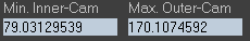 These values are useful to know when you want to make sure there is a minimum difference between the: •Bore-Radius and the minimum radius of the Inner Cam. •Plate-Radius and the maximum radius of the Outer Cam. X-Offset and Y-Offset When the Cam is stationary, enter an X-Offset and Y-Offset to move the center of the Cam-Plate relative the 0,0 of the Mechanism-Plane / Base-Part.
|
|
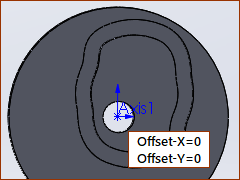 |
X Offset = 0, Y Offset = 0 Read-only if the Cam is a not stationary.
Image left: Blank-Radius and Blank-Bore with X-Offset = 0 and Y-offset = 0 |
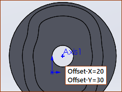 |
X Offset = 20, Y Offset = 30 Image left: Blank-Radius and Blank-Bore with X-Offset = 20 and Y-offset = 30 The maximum radius of the Blank-Bore can be increased, and the minimum radius of the Blank-Radius can be decreased. |
Notes: