Cam Life
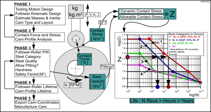
Work Flow - Phases to calculate the Cam Life.
Contact-Stress
To calculate the life of a Cam-Profile you first select a Follower-Roller in the Roller-Life tab. We can then calculate the contact-stress (Hertzian Stress) that is at the contact between the Cam-Profile and Follower-Roller.
To calculate the contact-stress we must calculate the contact-force from the addition of Inertia, Spring, Friction, Gravitational, Coriolis, and other forces as well as the influence of the Pressure-Angle between the Cam-Profile and Follower-Roller. The total force is usually different at each step in the machine-cycle.
The contact-stress is a function of the contact-force, materials, and geometric factors.
We calculate the contact-stress at each step of the machine cycle, from which we find the Maximum Contact-Stress.
You can apply a safety-factor (see Parameters tab), which we use to calculate the Dynamic Contact-Stress.
Steel Capacity
We must calculate the capacity of the steel - with which you propose to manufacture the cam - to resist contact-stress. The capacity of the steel is called the Allowable Contact-Stress of the steel.
We calculate the Allowable Contact-Stress when you select a steel-category, its quality, and enter its hardness. You can also apply a factor to many of the steel-categories that allows up to 15% of pitting to the cam's rolling surface.
There are 14 cast and wrought steel-categories, each with 3 steel-qualities. Each steel category and quality has a maximum and minimum hardness which define the limits of the hardness that you can enter.
Z-N Curve
We group the 14 Steel-Categories into Steel-Group #2, #3, or #4.
You can allow limited pitting to the Steel-Categories in Steel-Group #2, which then becomes Steel-Group #1. The Z-N plot for Steel-Group #1 is further to the right.
We calculate the parameter “Z” as the ratio of Dynamic Contact-Stress to the Allowable Contact-Stress.
We can then calculate from the Z-N curve for the Steel-Group and Steel-Category the number of machine-cycles, N, the steel can endure before rolling-contact fatigue results in pitting (or excessive pitting) and failure of the cam-surface.

Z-N Curves for different Steel Categories
Notes
Different steel categories have different Z-N curves.
1 × Life is at Z=1. The number of machine-cycles, N, for 1 × Life (Z=1) is different for different Steel-Groups.
2D-Cam > Cam Life tab
To Calculate Cam Life, you must :
Parameters tab
Cam Life tab
Review the Cam's Lifetime |

2D-Cam dialog > Cam Life tab
Cam Life: tab
Allow Pitting to ~15% of Cam Surface?
|
 Enter the Hardness as HB, HV, or HRC Select a Steel Category and Quality
Enter the Steel's Hardness within the High and Low Hardness Limits
|
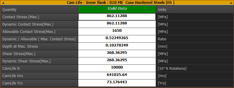
Cam-Life Results
NOTES ON CAM LIFETIME PLOTS
|
Steel Categories and Example Steels (mostly ISO 6336-5)
Examples Steels that PSMotion have assigned to the different steel and cast-iron categories. You must check that your steel is in the correct-category.
Steel / Cast Iron Categories |
Material Type (Abbreviation) |
Steel Quality |
Hardness Range |
Example Steels NOT from ISO 6336 |
|---|---|---|---|---|
Normalized Low Carbon Steels & Cast Steels (St (cast)) |
Wrought, normalized, Low Carbon Steels |
ML, MQ |
110 - 210 HB |
St50.2, 1.0050, E295 St60-2, 1.0060, E335 St70-2, 1.0070, E360 |
ME |
110 - 210 HB |
|||
Cast Steels |
ML, MQ |
140 - 210 HB |
GE200, 1.0420 GE240, 1.0446 GE300, 1.0558 |
|
ME |
140 - 210 HB |
|||
Cast Irons |
Black Malleable Cast Iron (pearlitic structure) (GTS (perl)) |
ML, MQ |
135 - 250 HB |
EN-GJMB-350-10 : HB 150 EN-GJMB-500-5 : HB 165-215 EN-GJMB-600-2 : HB 195-245 EN-GJMB-700-2 : HB 240-290 |
ME |
175 - 250 HB |
|||
Nodular Spheroidal Pearlitic Bainitic Ferritic Cast Iron (GGG (perl, bai, ferr)) |
ML, MQ |
175 - 300 HB |
EN-GJS-400-15 : HB 135-180 EN-GJS-500-14 : HB 170-215 EN-GJS-600-10 : HB 190-230 EN-GJS-700-2 : HB 210-305 EN-GJS-800-2 : HB 240-335 EN-GJS-900-2 |
|
ME |
200 - 300 HB |
|||
Grey Cast Irons (GG) |
ML, MQ |
150 - 240 HB |
EN-GJL-200, GG20 EN-GJL-300, GG30 EN-GJL-350, GG35 EN-GJL-400, GG40 |
|
ME |
175 - 275 HB |
|||
Through-Hardened Wrought Steels Nominally >0.2%C
|
Carbon Steels (V)
|
ML |
135 - 210 HV |
C40E, 1.1186 C45E, 1.1191, 1045,
|
MQ |
135 - 210 HV |
|||
ME |
135 - 210 HV |
|||
Alloy Steels |
ML |
200 - 360 HV |
42CrMo5, 1.7225 |
|
MQ |
200 - 360 HV |
|||
ME |
200 - 390 HV |
|||
Through-Hardened Cast Steels Nominally > 0.2%C
|
Carbon Steels (Low to Medium) |
ML, MQ |
130 - 215 HV |
100Cr6 |
ME |
130 - 215 HV |
|||
Alloy Steels |
ML, MQ, ME |
200 - 360 HV 200 - 360 HV |
G25CrMo4, G34CrMo4, G35CrNiMo6-6 G42CrMo4 :1.7231 |
|
Case Hardened Wrought Steels |
< 0.25%C (Eh) |
ML |
600 - 800 HV |
C14E/C10R/C15E/C15R/ 17Cr3 (1.7016, AISI 5115) 16MnCr5 (1.7131), 5115, 8620 18CrMo4 20MnCr5 (1.7147) 15NiCr13 (1.5752) 17CrNi6-6 (1.5918) 18CrNiMo7-6 (1.6587) 20NiCrMo2-2, 22CrMoS3-5 18NiCrMo5 17NiCrMo6-4, EN36 - 1.5752 - 14NiCr4, SAE8620, 14NiCrMo13-4, AISI 9310, 1.6657 655M13 EN39B(835M15), 15NiCrMo16-5, SNCM815. |
MQ |
660 - 800 HV |
|||
ME |
660 - 800 HV (58-64HRC) |
|||
Flame or Induction Hardened Wrought or Cast Steels |
>0.25%C
(IF) |
ML, MQ, ME |
485 - 615 HV 500 - 615 HV 500 - 615 HV |
34Cr4 (1.7033) (530M32) 41Cr4, 34CrNiMo6 43CrMo4(1.3563) |
Nitrided Wrought steels
Through Hardened, Nitrided |
Nitriding Steels |
ML |
650 - 900 HV |
EN40B, EN41B, 31CrMo12, 42CrMoV12, 38CrAlMo 31CrMoV9. 905M39 |
MQ |
650 - 900 HV |
|||
ME |
650 - 900 HV |
|||
Through Hardening Steels |
ML, MQ, ME |
450 - 650 HV 450 - 650 HV 450 - 650 HV |
32CrMoV13 |
|
Wrought Steels Nitro-Carburized |
Through Hardening Steels |
ML |
300 - 650 HV |
100CrMnSi6-4 (CarboNitriding) |
MQ |
300 - 450 HV |
|||
ME |
450 - 650 HV |
ML - limited demands on the material quality, number and type of inclusions, and on the material heat treatment process during gear manufacture.
MQ - requirements met by experienced manufacturers at moderate cost
ME - requirements realized when a high degree of operating reliability is required.
Refer to ISO 6336-Part 5 for ML, MQ, ME steels qualities.