Why should I use a Design-Set?
Use a Design-Set to edit a number of dimensions and parameters in one place - in the Design-Set dialog. Typically, add to a Design-Set those dimensions and parameters that you believe to be important to the outcome of a design objective, for example: to improve the Pressure-Angle of a Cam. Different Design Sets can be used for different purposes. When dimensions are in a Design-Set, you can ONLY edit them in the Design-Set dialog, and not model. A Design-Set can remind you and/or instruct other engineers which dimensions and parameters you should edit, or the opposite, those you should not edit. Give the Design-Set the name/caption - e.g. rename the Design-Set to “Do Not Edit!”. See also: Application-Settings > Graphics tab > Display Options | Show Function-Block names) |
Add Design FB
STEP 1Add a Design-Set FB to the graphic-data
 Design-Set in graphic-area The Design-Set FB in the graphics-area. Note: To show names of Function-Blocks as a caption, see Application-Settings > Graphics tab > Display Options | Show Function-Block names. |
|||||
STEP 2: Open the Design-Set dialog
 Double-click the Design-Set The Design-Set dialog is now open. STEP 3: See Design-Set dialog |
|||||
Notes : When you add a dimension to a Design-Set, you can edit the dimension only in the Design-Set. The dimension-lines and extension-lines of a Dimension are gray in the Part-Editor after you add it to a Design-Set. |
|||||
|
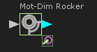
A Motion-Dimension FB is gray if you add the Base-Value parameter of the Motion-Dimension to a Design-Set. After you add the Base-Value to the Design-Set, the Motion-Dimension FB has a small icon at its bottom, right corner - see image. |
||||
See also: |
|
||||