3D-Cam
See Add 3D Cam
Note:
MD16+ : We do not immediately calculate the surfaces of a 3D-Cam when you open a file that has a 3D-Cam. To see the 3D-Cam, you must edit the 3D-Cam and click the button in the 3D-Cam dialog. To find a 3D-Cam element, browse the Assembly-Tree. |
 Cam-Part in the Graphics-Area |
It is not always possible to edit a 3D-Cam with a “double-click” in the graphics-area. Also, it is not always possible to edit a 3D-Cam with a “double-click” in the Assembly-Tree. It is best to edit the 3D-Cam from the Selection-Window.
|
|
 3D-Cam in the Assembly-Tree |
||
 Edit the 3D-Cam from the Selection-Window |
||
The 3D-Cam dialog is now open. |
||


3D-Cam dialog
 3D-Cam dialog |
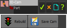
There are two buttons at the top of the 3D-Cam dialog: Click the button: •to build the 3D-Cam again and to show a change to the model. •before you save the 3D-Cam or export it to SolidWorks. Click the button to save the data for the surface of the 3D-Cam in different formats: •STEP, •SLDCRV, •TXT See more details below. |
There are three tabs in the 3D-Cam dialog: |
|
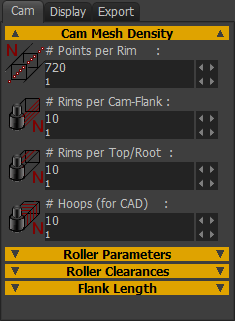
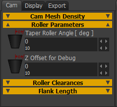
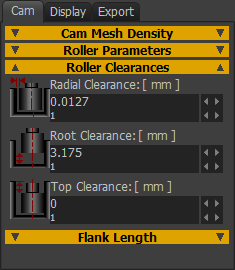
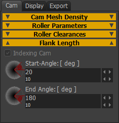
CAM tab
|
|||||||||||||||||||||||||||||||||||||||||||


DISPLAY tab
Preamble: The Display tab controls how you show the 3D-Cam in the graphics-area. |
|
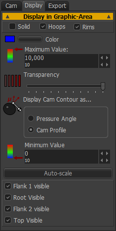 |
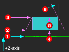
Solids* | Hoops | Rims. ☑ Solids*: show or hide, 3D-Cam as an MD-Solid ☑ Hoops: show or hide a hoop at each Point - see # Points ☑ Rims: show or hide the Rims along the 3D-Cam * You must enable the Solids check-box to see the 3D-Cam in other Mechanism-Editors and the Model-Editor Color •Use the Windows® color-picker to select a color of the 3D-Cam Transparency •Use the slider to change the Transparency of the 3D-Cam. Display Cam Contour as... •Pressure-Angle •Cam-Profile When you show the 3D-Cam as Pressure Angle, the faces have a color-code. •Red identifies a high Pressure-Angle •Blue identifies a low Pressure-Angle Minimum / Maximum By default, the color-code scales to the maximum and minimum values of the Pressure-Angle If you want to change the scale, use the Maximum Value and Minimum Value boxes. Auto-scale button Click the auto-scale button to reset to the maximum and minimum values again. Flank 1 visible, Root Visible, Flank 2 Visible, Top Visible Show or hide each surface |
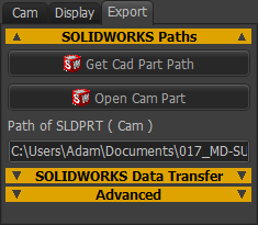
EXPORT tab
NOTE: From MD13.2, it is easier to save the 3D-Cam as a STEP file with the Save button.
|
||||||||||
REBUILD and SAVE buttons
 Export tab |
|
||
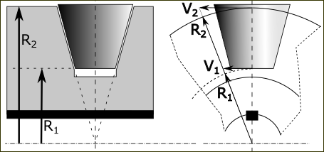
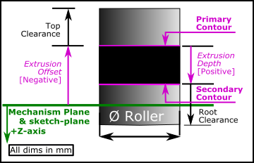
 Rims along the Cam-Flanks (Purple), the Top and Bottom (Orange), and Points along each Rim. |
Export 3D-CAM
| METHOD 1: Export the 3D-Cam as a STEP file (RECOMMENDED) |
 |
A STEP file-type is recommended. You can open a STEP file-type in most 3D-CAD programs. MechDesigner:
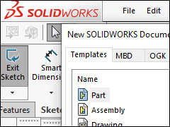
SOLIDWORKS STEP 1:Create a Solid model from the STP file.
|
||
 "Dissolve Feature" |
|||
 "Import Diagnostics" |
|||
 "Save the Cam" |
|||
 SOLIDWORKS: Cam-Blank |
SOLIDWORKS STEP 2:Open the Cam-Blank:
|
||
 SOLIDWORKS: Insert Part  SOLIDWORKS: Combine > Subtract |
SolidWorks STEP 3:Add the 3D-Cam (Cam.SLDPRT)...
If the Cam-Part is on the Front Plane (in MechDesigner) the Cam.SLDPRT ((3D-Cam) is usually in the correct orientation relative to the Cam-Blank.SLDPRT. If it is not, you must move the sketch (in SolidWorks®) of the Cam-Blank to the correct Plane. SolidWorks STEP 4:Cut the 3D-Cam from the Cam-Blank...
|
||
 SOLIDWORKS: Result |
Result:
|
||
Note: It is possible that the Solid Body “Cam<imported>” and Cam-Blank.SLDPRT are not defined on the correct Planes. In this case, redefine the sketch-planes of “Cam.Blank” (easiest method) or move “Cam<imported>” (more difficult to do) To move the sketch, you can
To move Cam<imported>, do:
|
|||
|
We usually recommend that you save the Cam as a STEP file - see METHOD 1 above. However, should you wish to use this method, do these Steps. STEP 1:In SolidWorks®,
|
||
 Click "Transfer Cam Blank" |
STEP 2:In MechDesigner - Transfer the Blank
See Getting Started Tutorials 6C for more information.
|
||
 Cam-Blank in SOLIDWORKS |
|||
 XYZ Curves, Surface, Knit features  Cam-Blank and 3D-Cam |
STEP 3:In MechDesigner - Transfer the 3D-Cam
|
||
3D-Cam cut into Cam-Blank |
STEP 4: Click Remove Surfaces from Blank button
STEP 5: Save the Part In SolidWorks®
|
||
 3D-Cam without Cam-Blank |