Reference Geometry
Terminology:
Reference Geometry : |
General term for the sketch-element that we copy from a different Mechanism-Editor to the active Mechanism-Editor when you do the command Add Reference Geometry. The two Mechanism-Editors are usually parallel. |
Source Sketch-Element : |
A sketch-element, in a moving or stationary Part, in a different Mechanism-Editor. |
Reference Sketch-Element : |
A copy of the Source sketch-element, and its motion, to a Part in the active Mechanism-Editor. |
Preparation
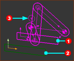 |
Preparation example: Two(2) Mechanism-Editors and Base-Parts: •Source •Reference In the image, there is a Circle This command can copy the Circle to the “Reference Mechanism-Editor”., which, in the image, is the active Mechanism-Editor. |
|
To see the sketch-elements and Parts in the “source Mechanism-Editor”: |
||
|
•Visibility toolbar (or menu) > Show other Kinematic and Sketch elements |
|
|
AND •Right-click Mechanism name-tab of the “Source mechanism-Editor” and select Show with 'other Kinematic and Sketch elements' ** |
|
|
AND •View toolbar > Spin or use your arrow keys on your keyboard to spin the model to see the two editors. |
|
** The first time you right-click a Mechanism name-tab, the text might be "Hide (when viewing in Background)". In which, right-click the message two (three?) times to select Show with 'other Kinematic and Sketch elements'.
Add Reference Geometry
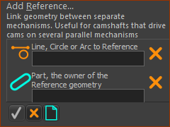 |
STEP 1:Start the Add Reference-Geometry command
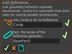
The Command-Manager indicates you must select two(2) elements. STEP 2:Select the two elements in the graphics-area
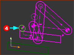
STEP 3:Complete the Command
Result :
|
|||||
|
||||||
 |
||||||
 |
Video:

Video: Add Referecne-Geometry