Cam Size
Terminology
Term : |
Definition |
Base Circle : |
The diameter of the smallest circle that is tangent to the Cam-Profile. |
Prime-Circle : |
The diameter of the smallest circle that is tangent to the Pitch-Curve. |
Cam Lift (STROKE) : |
The difference between the Prime-Circle and the maximum radius of the Pitch-Curve. |
Inner Cam : |
For rotating cams, it is the cam that is nearer to the rotating center of the Cam-Profile. |
Outer Cam : |
For rotating cams, it is the cam that is further away from the rotating center of the Cam-Profile. |
Pitch-Curve : |
The trace of the center of the Follower-Roller relative to the cam. |
Cam Size: Measure with a Measurement FB
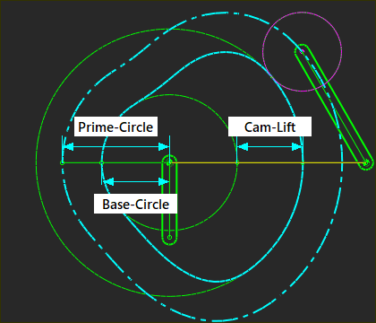 Measuremnt FBs to measure the Base-Circle, Prime-Circle, and Cam-Lift. |
Use a Measurement FB to measure these three dimensions of a Cam-Profile. Base-Circle - radius The Base-Circle is the minimum radius of the Cam-Profile. 1.Click Kinematic FB toolbar > Measurement FB (or Function-Block menu > Measurement) 2.Click the Contact-Point between the Follower-Roller and the Cam-Profile 3.Click a Point at the center of the Cam-Shaft 4.Click the graphics-area to place the Measurement FB 5.Cycle/Jog the model until the Measurement is a minimum ... you have found the radius of the Base-Circle Prime-Circle - radius The Prime-Circle Radius = Base-Circle Radius + Follower-Roller Radius 1.Add the radius of the Follower-Roller to the Base-Circle or 1.Add a new Measurement FB to measure between the center of the Cam-Shaft and the center of the Follower-Roller Cam-Lift (Stroke) The difference between the minimum and maximum radii of the cam is the Cam-Lift (also called its Stroke). 1.Rotate/Jog the model until the Measurement is a minimum and make a note of the dimension 2.Rotate/Jog the model until the Measurement is a maximum and make a note of the dimension 3.Subtract the dimensions. |
Advantages and Disadvantages of a Small Cam.
When there is a tool motion that is fixed, and a kinematic-chain that moves the tool, then we can consider the absolute and relative effects of a cam's size. Advantages of a small Cam. A small cam: •decreases required space •decreases manufacturing cost - however, machining accuracy may be more problematic with an extremely small cam. •decreases inertia to start and/or stop rapidly •decreases out-of-balance force (if you do not balance the Cam) •decreases Follower-Roller RPM - if you use the same roller diameter Disadvantages of a small Cam. A small cam: •decreases the flywheel effect - a flywheel helps to rotate the cam-shaft with a constant angular velocity. •decreases the radius-of-curvature, which increases the Hertzian Contact-Stress and chance of undercutting. •increases the radius ratio between the pivot point of a follower. •a smaller cam relative a fixed mechanism size may increase the mass and decrease stiffness when referred to a follower-roller. |