A Typical Mechanism in a Packaging Machine

Typical Mechanism
This is a typical mechanism that you will find in many packaging, textile, and assembly machines.
The lowest natural frequency determines the overall performance of the mechanism mechanism.
Lowest natural frequency.
We will model it as a Single Degree-of-Freedom model.
To find its lowest natural-frequency:
•Evaluate the Mass, Mass Moment of Inertia, and Stiffness of each part.
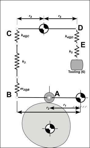
•Refer them to one point in the mechanism as a single Equivalent Point Mass and Equivalent Stiffness - in this example, we refer them to the Follower-Roller (see image below)
•Calculate the lowest natural frequency from the Equivalent Mass and Equivalent Stiffness values.

Equivalent Mass

Equivalent Stiffness
Or
•Evaluate the Mass Moment of Inertia, and Rigidity of each Part
•Refer them to one point in the mechanism as a single 'equivalent' Mass Moment of Inertia and Rigidity - in this example, refer them to the Follower-Roller
•Calculate the lowest natural frequency from equivalent Mass Moment of Inertia and Rigidity values.
All parts are Steel, .,
STEP 1- Evaluate the Mass and Effective Masses as a “Lumped-Masses”
 Lumped Masses Only Model
|
Tooling, (6) Mass (from CAD)
Short Push-Rod, (5) Mass (from CAD)
Lever, (4) rotates about Radius: Mass Moment of Inertia about : (from CAD) Refer the Mass Moment of Inertia as an equivalent Mass at
Long Push-Rod, (3) Mass (from CAD)
Follower, (2) rotates about Radius: . Mass Moment of Inertia about : (CAD) Refer the inertia as an equivalent mass at point
Follower-Roller, (1) The mass of the is found from the bearing catalog.
|
STEP 2 - Refer the Lumped-Masses to the Follower-Roller at A
Tooling (6) and Short Push-Rod (5) Add the mass of the and the
Refer the mass at to Use the square of the ratio of the radii : , Alternatively, we can equate the Mass at D to a Mass Moment of Inertia at O4, then refer that Mass Moment of Inertia as a Mass at C.
Add the Effective Mass of Lever (4)
Add the mass of the Long Push-Rod Add the mass at to the mass of the , , to point .
Add the Effective Mass of the Follower
Refer to the Follower-Roller Refer the Mass at to the at , and add the Mass of the Follower-Roller.
This is the Effective Mass we need to find the Lowest Natural Frequency. |
STEP 3 - Evaluate the Spring-Rates as “Lumped Springs”
|
Tooling, 6 Assume to be infinitely stiff. Short Push Rod, 5
; Length :
Right-side of the Lever 4, at D From FEA in CAD Fix: and ; Vertical Load:
Left-side of the Lever 4, at C From FEA in CAD FEA: Fix and , Vertical Load:
Push-Rod, 3 The Push-Rod is a steel tube with OD of 25mm and ID of 18mm. Area: . Length:
Follower, 2 From FEA in CAD Fix: and ; Vertical Load:
|
STEP 4 - Refer the “Lumped Springs” to the Follower-Roller.
Combine spring-rates and Springs in Series
Move to Refer at to
Combine spring-rates , , and Springs in Series
Refer Spring-Rates at B to A Refer to
This is the Effective Stiffness we need to find the Lowest Natural Frequency. |
Calculate the Natural Frequency
Using Mass and Stiffness
Using Mass Moment of Inertia and Rigidity
Units
|