This topic describes how you can calculate the values for an Asymmetric Rise or Return Segment.
See the on-line Getting Started Tutorials: MotionDesigner to see how you can design an asymmetric segment with MotionDesigner.
First, we can look at normalized symmetric rise segments.
6 Normalized Symmetric Rise Segments

Normalized Displacement Plots of 6 different motions laws, with zero-velocity at the start and end of each.
The image above shows 6 normalized symmetric rise segments motion-laws.
While the motion-laws are clearly different, their common characteristics are as follows:
Period : |
|
Rise displacement : |
|
Zero velocity at the start and end of the segment : |
|
Zero acceleration at the start and end of the segment* : |
|
Maximum velocity at the mid-point of the segment : |
|
Equal acceleration and deceleration periods :
|
|
Asymmetry Factor: |
|
* Zero acceleration at the start and end of good motion-laws, while others, e.g. the Parabolic† motion-law, may have acceleration discontinuities. † Parabolic motion-law is another name for the Constant-Acceleration and Constant Deceleration motion-law. |
|
Normalized Symmetric Segment
The image below shows the normalized displacement, velocity, and acceleration plots for the symmetric Parabolic motion-law, in which the Asymmetry Factor is , that is, it is Symmetric.
You can see that the:
•Acceleration phase is from , and the deceleration phase is from . The period of the phases are equal to each other.
•The inflection point of the displacement plot is at maximum velocity and as acceleration changes to deceleration. It is also on the diagonal .
•The Asymmetry Factor, .
0

Symmetric Nomralized Parabolic Rise Segment
Normalized Asymmetric Segment
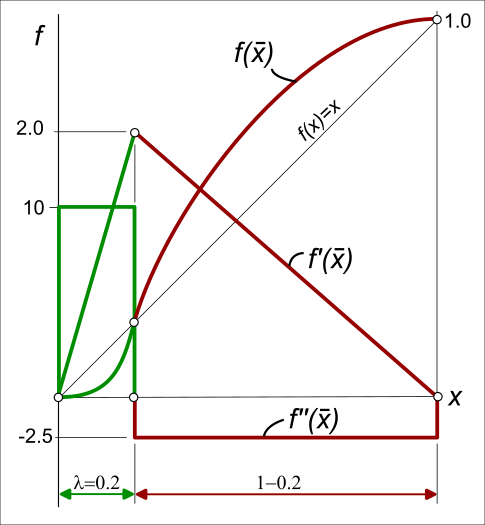
The image below shows the normalized displacement, velocity, and acceleration plots for an asymmetric Parabolic motion-law, in which the Asymmetry Factor is .
In the example:
•Acceleration phase is from , and the deceleration phase is from
•The maximum normalized acceleration values have increased from 4 (symmetric) to 10 (asymmetric).
•The maximum normalized velocity values of the symmetric and asymmetric segments are equal to each other.
•The inflection point of the displacement plot is on diagonal:
•The Asymmetry Factor, .
How to calculate the motion values of an Asymmetric Motion Law
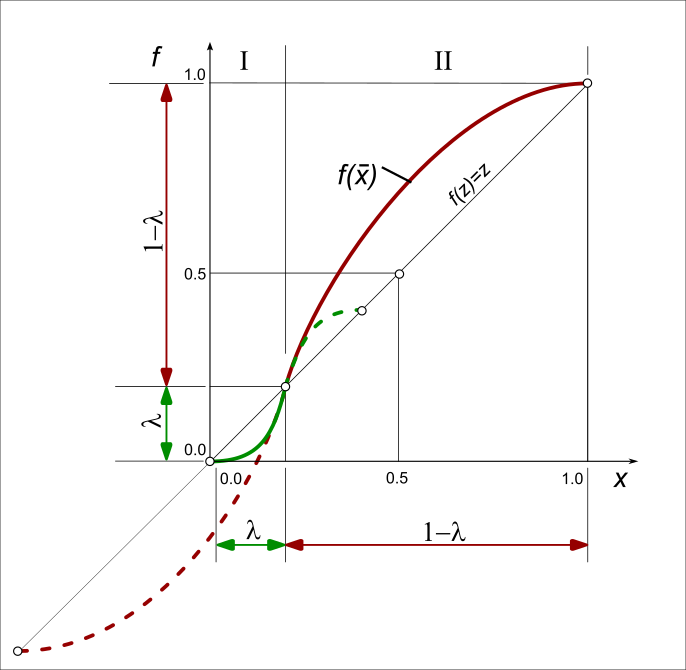
It is helpful to imagine that the asymmetric motion as two half segments, or phases.
The X-axis and Y-axis of the solid green plot are from - it is the acceleration phase of the asymmetric motion.
Hence, to calculate the values for the solid green part of the segment, we need to “shrink” the X-axis and Y-axis.
The X-axis and Y-axis of the solid red plot are from - it is the deceleration phase of the asymmetric motion.
Hence, to calculate the values for the solid red part of the segment, we need to “stretch” the X-axis and Y-axis.
The factors for the “shrink” Phase () and the “stretch” Phase (), are below.
Phase :
Scale the X-axis to |
|
Use to calculate and scale the displacement |
|
Use to calculate |
|
Use to calculate and scale the acceleration |
|
Phase :
Scale the X-axis |
|
Use to calculate and offset and scale the displacement |
|
Use to calculate |
|
Use to calculate and scale the acceleration |
|