There is often a need for the motion-values of a Motion Law to start and end:
•at two different positions,
•with two equal velocities, potentially non-zero velocities
•and with zero accelerations.
The Flexible Polynomial motion law, that is preceded and followed by Constant-Velocity segments, is easily configured with these motion constraints.
Occasionally, however, you may want a velocity at the start and end of a Traditional Motion-Law, such as a Mod-Sine. You cannot do this directly with MotionDesigner.
To get round this problem, you can add a Constant-Velocity motion to a Mod-Sine motion. This topic describes how you can do this with a Math FB. You can add any motion to any other motion, and you are not limited to two motions.
Notes:
Care must be taken to use consistent units. The math in the Math FB uses SI units, e.g radians, or meters. You can edit the Motion FB to select the data-type at its output as Motion, Linear, or Rotary. However, when it is to be connected with a wire to the input of a Math FB, you should select Linear or Rotary as the output data-type. Do NOT select “Motion” as the data-type. |
A MechDesigner Model to add two Motions
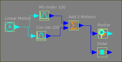
The Function-Blocks and wires.
The image below shows wires that connect the output from two Motion FBs to the input of one Math FB.
The Motion FB
You muse edit the Motion FB to change Output Data-Type to Linear or Rotary.
Note: blue wires indicate the data-type is set to Linear.

Motion FB - Output Data-type
The Math FB
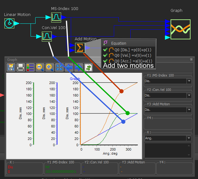
The equations for the three data-channels in the Math FB add the position ( p(0)+p(1) ), velocity ( v(0)+v(1) ), and acceleration ( a(0)+a(1) ) values of the two wires at the input to the Math FB.
The Output Data-Type from the Math FB is set to Linear Coordinates - which are [Dis.], [Vel.], and [Acc.], which are Linear units.
Wires connect the Motion FBs and the Math FB to a Graph FB to give graph plots.
•The Green plot is the displacement for an indexing motion linked to a Motion FB - it indexes by 100 mm in one machine-cycle.
•The Blue plot is the displacement for a constant-velocity motion linked to a Motion FB - it increases by 100 mm in one machine-cycle.
•The Orange plot is from the Math FB - it shows the addition of the two motions from the two Motion FBs - it increases by 200 mm in 1 machine-cycle)
You can connect wires from the Math FB to a Motion-Dimension FB for a Slider or a Rocker.
If I was to connect the output to a Rocker, edit the Motion FBs to change the output data-type to Rotary and also edit the Math FB to change the Output Data-Type to Rotary Coordinates.