Objective of this Step.
You will edit the “Crank-Slider” to be an “Offset Crank-Slider”. You will explore the Kinematics-Tree and the elements : •Rocker (Motion-Part) •R-R-P dyad You will use the Kinematic elements toolbar (or Function-Blocks menu) > Change Dyad Closure command to see: •4 × Closures of the “Offset Slider-Crank” and R-R-P dyad You will understand why and when: •Dyad-closures can solve (Valid) •Dyad-closures can not solve (In-Valid)
|
Important:
In general, all 4 × Dyad-Closures can be Valid for all positions (angles) of the Crank, or Valid for only a range of positions of the Crank. Cycle the model after you change the Dyad-Closure to make sure the Parts can be solved (that is, a valid Closure) for all angles of the Crank, or at least the range of angles you need the dyad to solve in your design. |
Terminology
Term : |
Definition |
|---|---|
Machine-Cycle : |
The MMA changes by 360. |
Motion-Part : |
A Part whose position we control with a Motion-Dimension FB. |
Rocker : |
A Motion-Part whose angle we control with a Motion-Dimension FB. |
Crank : |
A Rocker whose angle changes with a uniform angular velocity. |
Rotating-Part : |
A Part that you join with a Pin-Joint to a different Part. |
Sliding-Part : |
A Part that you join with a Slide-Joint to a different Part. |
Dyad : |
A dyad is a kinematic construction of: •2 Parts and •3 Joints |
Dyad Closure : |
A different way to assemble the two Parts in a dyad. |
Crank-Slider Mechanism: |
A kinematic-chain with a continuously-rotating Crank, and a dyad that has two Pin-Joints and one Slide-Joint. There is a sliding-Part that reciprocates back and forth, and a connecting-rod that connects the sliding-Part to the Crank. |
Offset Crank-Slider Mechanism : |
A Crank-Slider Mechanism in which the Pin-Joint (x-R-x) of the R-R-P dyad is offset from the Slide-Joint (x-x-P) |
Kinematics-Tree Symbols
|
Unrestricted Dyad Closure : |
The dyad can solve throughout the machine-cycle. |
|
Restricted Dyad Closure : |
The dyad cannot solve for a period within a machine-cycle. |
|
Broken dyad : |
The dyad cannot solve now at this machine-angle. |
Videos
The two videos, below, show the dyad-closures when they are valid and Invalid. As you look at these videos, identify the Motion-Part. The Motion-Part ALWAYS moves with the motion-values that are at the input-connector of the Motion-Dimension FB. The videos show: the Valid and Invalid dyad closures of the R-R-P dyad.
Video 1: CRANK + R-R-P dyad - 4 VALID ClosuresR-R-P dyad : 4 Valid Closures Video 2: CRANK + R-R-P dyad - 2 VALID & 2 INVALID ClosuresR-R-R dyad - 2 Valid Closures and 2 Invalid Closures
|

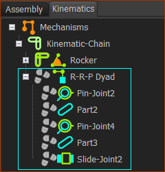
Kinematics-Tree and the R-R-P dyad
|
Expand the Kinematics-Tree
|
Change the “Crank-Slider” to an “OFFSET Crank-Slider”
|
STEP 1: Edit the sliding-Part
The sliding-Part opens in the Part-Editor |
|||
|
STEP 2: Add Geometry - a short Line
STEP 3: Add Constraints
STEP 4: Delete the Pin-Joint
The two Parts are again not kinematically-defined (not solved). * If you cannot click the Pin-Joint only, then, as described in detail in Step 2.3: •Delete the Pin-Joint with the Selection-Window or •Delete the Pin-Joint from the Assembly-Tree |
|||
|
||||
 Click the Pin-Joint ONLY |
||||
|
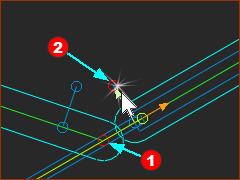
STEP 5: Move the sliding-Part; Add the Pin-Joint again.
The R-R-P dyad is again complete. The three Joints in the dyad are:
Now we use the term Offset Crank-Slider. Is this the dyad-closure you want? Save your Mechanism : CTRL+S |
|||
|
Offset Crank-Slider: The Valid and Invalid R-R-P Dyad Closures
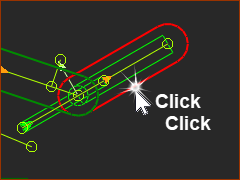
Four Valid Closures
|
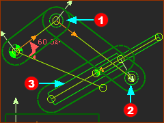
In the image you can see: 1 x Arc 2 x Lines In the image you can see that the Arc and Lines intersect in four places. 4 x These are the positions of the Pin-Joint |
 Closure 1  Closure 2  Closure 3  Closure 4 |
|
Two Valid Closures and two Invalid Closures |
|
If when you add the final Pin-Joint to complete the R-R-P dyad, |
|
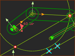 |
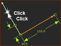
In the image you can see 1 x Arc 2 x Lines In the image you can see that the Arc intersects one of the Lines. 2 x These are the positions of the Pin-Joint |
Two Valid Closures and two Invalid Closures
If, when you add the final Pin-Joint to complete the R-R-P dyad, the Parts do not solve, cycle the model to see if there is an angle of the Crank in which the Dyad can solve. |
|
|
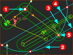
In the image you can see 1 x Arc 2 x Lines In the image you can see that the Arc intersects one of the Lines. 2 x These are the positions of the Pin-Joint |
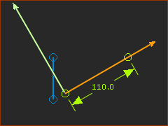
Change Dyad Closure of the OFFSET R-R-P dyad.
 Dyad Closure 1- RRP  Dyad Closure 2 - RRP  Dyad Closure 4 - RRP  Dyad Closure 3 - RRP |
STEP 1: Start the Change Dyad Closure command
The Command-Manager starts. It has one selection-box. You must select a Part from the dyad STEP 2: Click a Part-Outline
STEP 3: Complete the Command a Part-Outline
STEP 4: Repeat the Commands
The images show the four closures of the Offset R-R-P Closures. |